
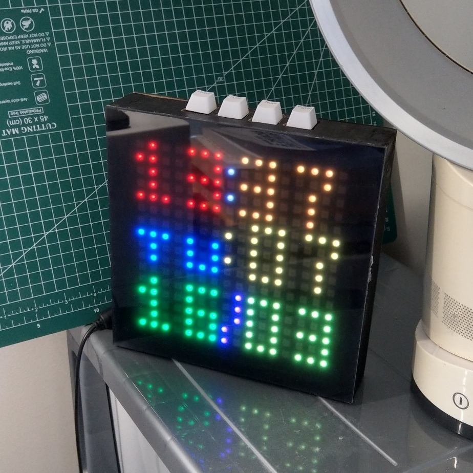
After around 2 years, my first (presentable) DIY project is finally complete! It’s a device with a 16x16 LED matrix display, which is primarily used to display time. It’s also WiFi-connected, syncs time via NTP, can have 3 alarms, and potentially do more interesting stuff with its internet capability.
So, this post will document the process of me making this thing. I didn’t have many mishaps, the process is relatively smooth, and the reason it took so long is mostly me procrastinating.
For a lack of name ideas, I used a random pet name generator online, and it gave me the name "Baby Tiger". This is probably not the best name for a digital clock (it sounds like a very generic name for a cat), but I have no better ideas. Name suggestions are welcome.
The Electronic Components
I guess it’s because of watching YouTubers like GreatScott!! and DIY Perks piqued my interest and I wanted to make something of my own. And a clock with LEDs sounded like a fairly conservative thing to make that would not present much trouble, since similar hardware and design patterns seems to be done by others a lot. So with this thought, and the knowledge from YouTube videos that a kind of microcontroller[1] called the Arduino would be suitable for controlling LEDs, I bought an Arduino Nano knockoff[2], breadboard[3], jumper wires and RGB LEDs.
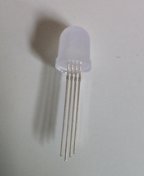
This RGB LED is a package of 3 LEDs of colors red, green and blue. I need to power each color individually in order to display different colors. I made it to work, but there were big catches:
- I can’t adjust the brightness of each color components directly, so I can only have the primary and secondary colors, plus white and black (off). I had to use PWM[4] in order to make fancier colors.
- The weirder problem was this RGB LED is unlike just 3 LEDs in parallel, the red, green and blues LEDs can’t be on simultaneously, which means I had to do PWM faster and the software needs to be a little more complicated.
- Each LED consumes 3 pins for the 3 color components. I was making a clock, so there eventually needs to be a large quantity of LEDs connected before displaying anything resembling time. There aren’t that many pins on an Arduino Nano. I learned about shift registers that can "expand" the number of controllable pins, but then I had to do PWM with software which felt very complicated. Shift registers will also make outputs slower, combined with the issue above, I was afraid that the speed of an Arduino Nano wasn’t fast enough.
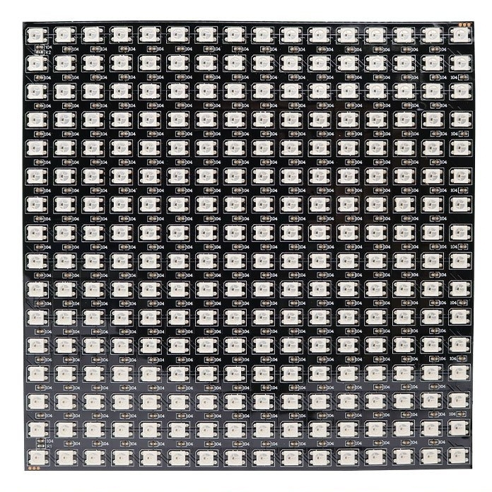
I complained about this online and prepared to buy some shift registers to try nevertheless, then someone online suggested me to take a look at a more sophisticated RGB LED called the WS2818B. I looked it up, and it seems like a very popular choice of RGB LED. With a WS2818B, it will only need a single data pin to receive the color data, and will retain the color without the controller doing PWM. It also appears that those things can also be chained so I can have theoretically as much LEDs as I want, using just a single pin to transmit color. These features compared to the original LEDs, sounded like driving a car compared to crawling. I was carried away, and thought of expanding the project into something fancier.
I won’t make any regular old digital clock, I wanted make it to have a matrix of LEDs that functions as a screen, so that it can display more interesting things than just time. Coincidentally, I saw a product listing of 16x16 WS2818Bs pre-made into a matrix, which sounds like exactly what I want, saves me the trouble of laying out the total of 256 LEDs and soldering them.
As I researched, the device won’t function with just a microcontroller and 256 LEDs. It will also need these less important, but still necessary things to be a decent clock:
- A power supply. Both the Arduino Nano and the WS2818B matrix wants 5V power. According to an article I read online, a single WS2818B LED can draw 50mA of current, which sounds small. But I have 256 of them, so it multiplies to 12.8A. I couldn’t find a mains power supply that converts to 5V and is rated for more than 12.8A. What I was able to find were a mains to 12V power supply that can carry that much power, plus a converter that converts those 12V into 5V. The 12V-to-5V converter can only carry 10A though, but according to the article mentioned above, 50mA is just a maximum, so as long I don’t run it at full brightness and every pixel being white, it should be fine.
- 5.5mm DC power barrel jack. This allows the 12V power supply to connect to the input of the 12V-to-5V converter.
- DS1307 RTC module. This module keeps the clock running in the background, even when power is disconnected, so I would not need to set the time every time power is reconnected. I suppose it may also a bit more accurate than counting the time with the Arduino’s internal CPU clock.
- More wires and breadboard.
At the same time, I came across something called an ESP8266. They say it’s similar to an Arduino, but it can connect to WiFi. I then excitedly decided to use that as the central microcontroller and ditched the now-dumb-looking Arduino Nano, and started daydreaming about the potentials of having internet access: I could synchronize time from the internet, and possibly displaying messages and notifications, even stream videos! (Yes, I know, playing a video on a 16x16 screen is extremely impractical. It could probably play Bad Apple though, which sounded pretty cool to me.)

Now the project has become more ambitious, I started to think of even more features that I could add to this clock.
Displaying current temperature? Yes, let’s add a temperature sensor.
Having the ability to sound alarms? Yes, let’s add a buzzer.
Buttons too small and ugly? Let’s use the 4 Cherry MX key switches[5] I happened to have lying around instead of regular small tactile buttons, and use some custom key caps which I’ll worry about later.
So here are the aforementioned things I ended up having inside the clock, plus some other details:
(This photo was taken after the whole thing has been built, it obviously didn’t look like this at that stage. They were stuff plugged onto breadboards, I have a photo of that later in the article, but that photo wasn’t suitable for explaining what the components are.)
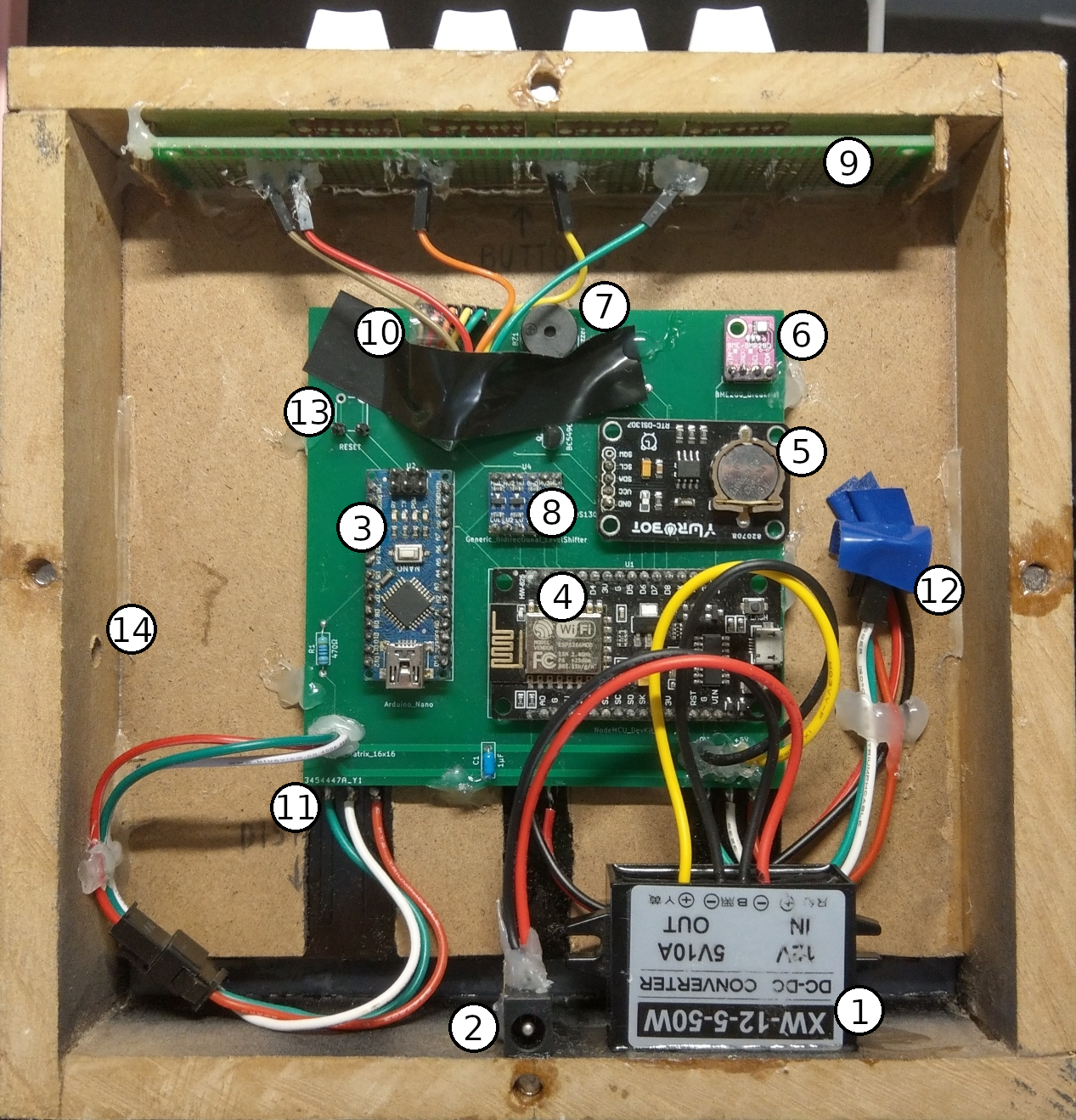
① 12V-to-5V DC converter
② 5.5mm DC barrel jack
③ Arduino Nano
④ ESP8266
⑤ DS1307 RTC module
⑥ BME280 temperature sensor
⑦ Buzzer
⑧ 5V-3.3V bidirectional logic level shifter, this allows the components operating at 3.3V (ESP8266 and BME280) to communicate with the components operating at 5V (others) without blowing up
⑨ The board that holds the 4 keys of the device, a.k.a. key board, not to be confused with a computer keyboard
⑩ Where the key board connects to the main board
⑪ Where the 16x16 LED display connects to the main board, the display is on the other side (front)
⑫ Unused connections of the display glued to the box so they don’t get in the way
⑬ Unused connections of a reset button, I decided later that this is unnecessary for normal use
⑭ Unused hole where the reset button was supposed to be
Why do I still have an Arduino Nano in the picture above? Didn’t I say I ditched it? Well, it turns out that controlling 256 LEDs with 1 pin requires a lot of work from the microcontroller. It requires very precisely timed signals so the microcontroller can’t do anything else during signal transmission, which is bad if I want to have WiFi connected because it requires some WiFi stuff to be constantly done, I also want time for my own code to run. There are tricks to use dedicated hardware to transmit these signals, but they either consume too much memory, or occupies the pin I need for other purpose. So I put the Arduino Nano back, and programmed it so that when the ESP8266 wants to update the display, it transfers the display data into the Arduino Nano, the Arduino Nano then does the time-consuming job of transmitting precisely-timed signals, while the ESP8266 carries on doing more important things. Was is a waste to put a whole Arduino just for this singular purpose? I suppose so, but it was the easiest way of solving my problem.
The Software
After I have got those components on the breadboard and connected (it didn’t look like the picture above, it was just on the breadboard), I started programming the software.
First, I decided the interactions I could have with the clock. It will have 4 buttons:  ,
,  ,
,  ,
,  . When it’s powered on, it will display the current time (I’ll call it "clock mode"), pressing will turn off the display, and pressing will bring up the main menu, where the various additional functionalities (like alarms and settings) can be selected. and changes the selection, confirms the selection, and returns to an upper-level menu or the default clock mode.

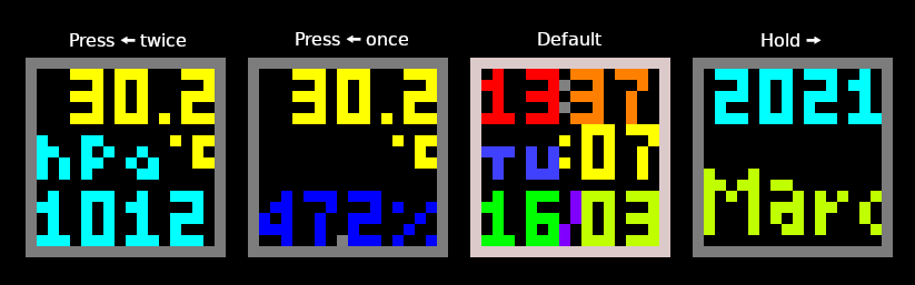
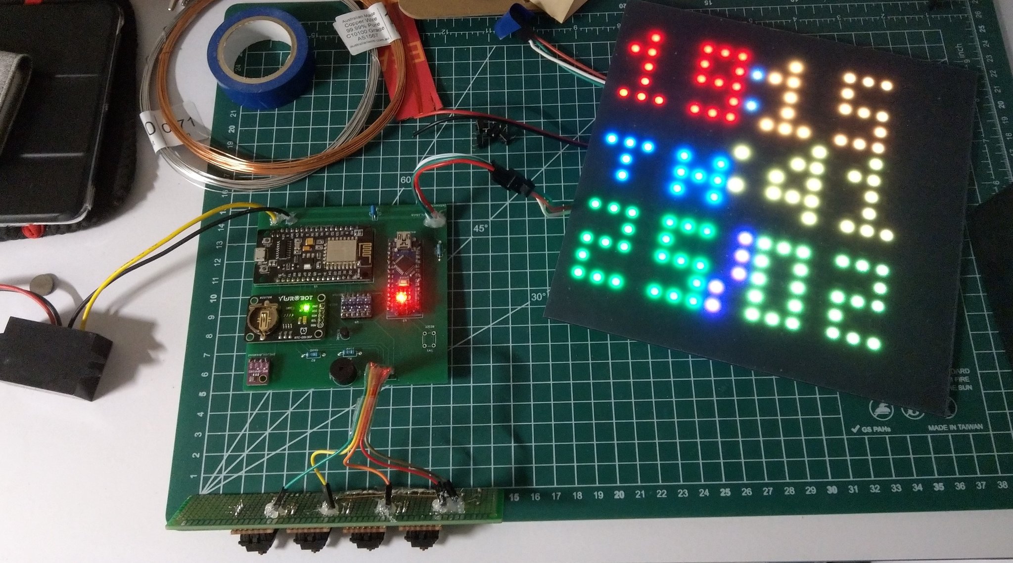
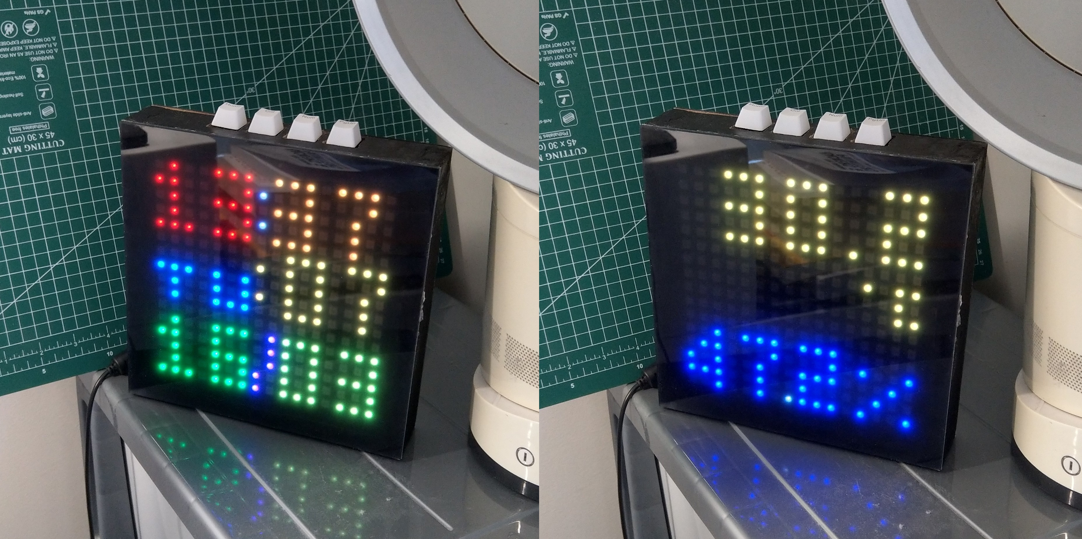
While making the clock mode, I realized that there isn’t enough pixels to display everything about the current time. A 0-9 digit takes at least 3x5 pixels, each 2 digits needs to have 1 pixel between them so they don’t fuse together. It ends up being a little challenging. I have to use different colors for different parts of the time for them to look distinct. I made a separate screen to show the year number and month name when is held down. Pressing will on the other hand switch the time display into temperature/humidity and temperature/pressure obtained through the BME280 temperature sensor.
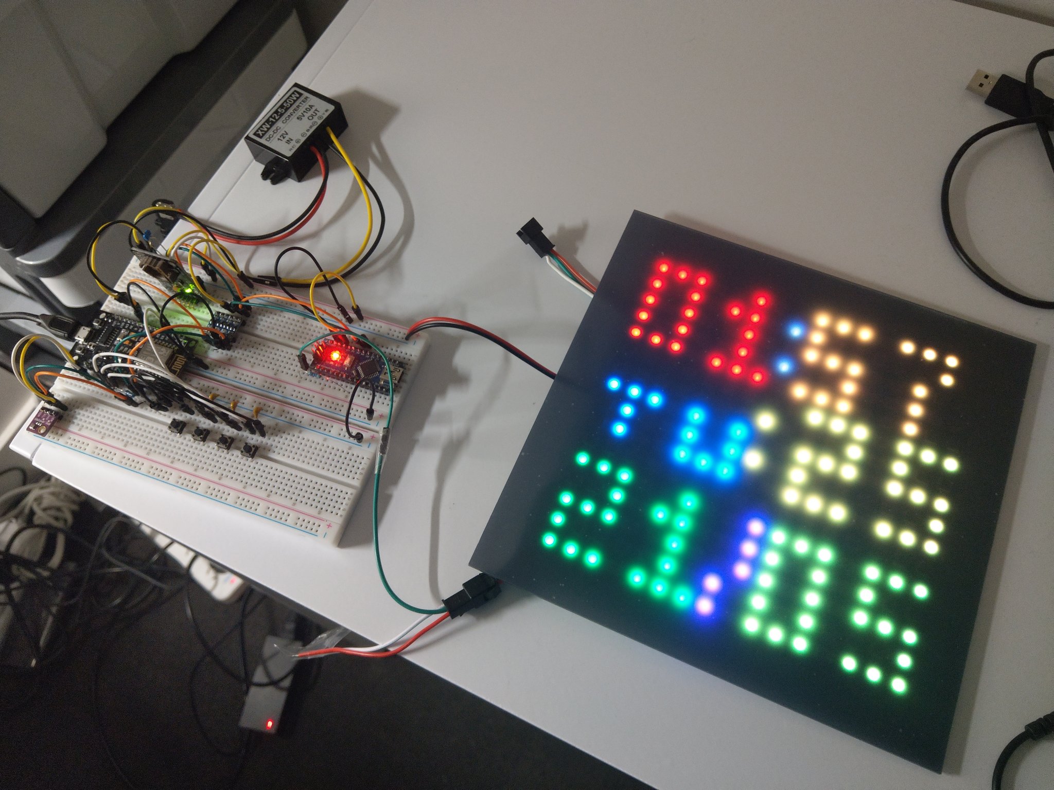
At this stage, I was pretty happy about what I have accomplished, so I posted its photo on social media.
Afterwards I made the main menu (and by afterwards I mean 1.5 years later, yes I procrastinated for that long). It shows the name of the menu item at the bottom half of the screen. Right now they are Alarms, Games and Settings. Since the screen is so small, only one option is shown at a time, and the text scrolls from right to left.
The settings menu consists of these options:
- Time: Setting the current time manually. There aren’t much to be noted, except writing the UI interactions were kind of tedious. Anyways, it works.
- Timezone: Because I use NTP to synchronize time with the internet, and NTP only cares about UTC, I have to take care of the local time offset locally, which is changed from here.
- NTP: I originally planned to make an On/Off switch for NTP, but didn’t ended up bothering, so right now it just shows the last synchronization time, and if there is an error synchronizing.
- WiFi: Setting the SSID and password of the WiFi network to connect to. Since the clock does not have a keyboard to type those things, I have to do it the around-about way: Let the ESP8266 make a WiFi access point for a phone to connect to, present a web page for inputting the SSID and password, receive them from the phone through HTTP, and finally try to connect to the network. Writing code for this process was the most tedious of them all (I wrote an HTTP server from scratch!). It eventually worked, kinda, although I don’t dare looking at the spaghetti code I wrote ever again.
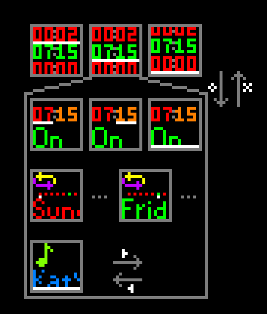
In the alarms menu, I made 3 alarm slots. The enabled alarms are green, while the disabled ones are red. Since I don’t have enough vertical pixels to display 3 rows of timestamps, the last alarm will have its last bit cut off, and everything will get shifted up when the last alarm is selected. Going into an alarm setting (by pressing ) will let me change the hour, minute, on/off, whether it repeats on each day of of a week, and which music to play when the alarm triggers. It ended up looking pretty good, if I do say so myself.
I originally planned to put some games on there, but they aren’t exactly necessary, and seemed like a lot of work, so in the end I didn’t write any. The "Games" on the main menu is just the demo music player that plays Senbonzakura.
I mentioned 2 musics that’s on Baby Tiger, Senbonzakura and Katyusha. They aren’t really musics though, as I could only play square waves from a ESP8266. It can’t play regular music file, nor does it play MIDI. These 2 tracks are just notes I typed into the code manually. (I really should write a script to convert from MIDI, if I really want many different music to select from. Doing this by hand is pretty time-consuming.)
And then I felt like the software was done enough. So the next step is to figure out how put them in a good-looking enclosure. But before that, I got to move the electronic component out of the wobbly breadboard, onto a more sturdy circuit board.
The Circuit Boards and Keys
So the plan was to have 2 separate circuit boards connected by a ribbon cable. One was going to be the main board, holding most of the stuff; the other was going to be the key board, holding the 4 key switches, as well as the capacitors and resistors for debouncing.
Let’s talk about debouncing[6]. There are 2 ways of debouncing, hardware and software. I chose hardware because the article I read to learn about the topic said "It’s a hardware problem, so it’s best to be solved with hardware." and I agreed that hardware feels more elegant. The problem is, I don’t have an oscilloscope, so I just had to guess how long and how often the buttons bounce, and in turn had to guess the capacitance and resistance values in the debouncing circuit. The guesswork was a weird experience. The idea of hardware debouncing is to let the capacitor charge or discharge slowly when the button is pressed or released, so even if it bounces a little, the voltage would not change too much as to let the microcontroller think as extra button presses. That means the bigger the capacitance, the bigger the resistance, the slower the voltage changes, so the less likely for the bounces to have an effect, with the trade-off of the button press feeling more laggy, right? Well maybe my understanding is wrong, because changing to bigger capacitor apparently make the bouncing worse than having a small capacitor. Changing resistors could also make it worse – or better, it feels completely random, and the ESP8266 is so weird that some pins seems to work the best with different valued resistors than other pins. I still couldn’t understand why that is, maybe the answer will be more apparent if I had an oscilloscope. Eventually though, I figured out a circuit that worked well enough.

I didn’t plan to draw and order a custom-made PCB, I thought just soldering stuff onto a perf board[7] should work well enough for my purpose. I was wrong.
I started out making the key board since it’s the simpler of two. Then I realized what appears to be simple on a YouTube video may not be so simple if I do it myself. Those YouTubers had experiences and I didn’t. The process of realizing the circuit diagram above was slow and painful. I couldn’t keep the components in place before soldering them, it ended up resulting in none of the key switches are seated nicely, they tilted in all different directions. It’s really unideal, but what’s been done is done, I can’t do it again unless I buy new key switches. It was also difficult to make the wires connect to where I want them to connect to while not touching where I don’t want them to have contact with. After I finished making the key board, I concluded: There is no way I can do this manually for the much more complicated main board.

Defeated, I sat back to the front of the computer, and decided to draw a PCB with KiCad. I didn’t know how to draw PCBs, but luckily it didn’t take too much time to learn with the help of guides found online. And I was glad to not go down the manual perf board soldering path, because the PCB I ended up drawing looked like this: They are all necessary connections.

I sent the PCB design to a company that makes custom PCBs for individuals. The board itself was not very expensive, costing US$ 4, but the shipping though, they cost $14 and was estimated to take about a month. The DHL express shipping costed $21 but is estimated to take less than a week. I chose the latter. The slow shipping was already that expensive, so it felt justifiable to buy the 1.5 times as expensive but 4 times as fast shipping method.
It took less than a week to arrive, as expected from DHL. I then soldered all the remaining components, completed with significantly less sweat than when I made the key board.
Now comes the moment of truth: If I drew the PCB wrong, then things will not work and I’ll have to spend $25 again. Or worse, I’ll blow up components. Luckily nothing seemed wrong as I plugged in power – a successful milestone.
The Enclosure
It was the time for the non-electronic part: making an enclosure for everything to sit nicely and look good in. In my imagination, I figured that the shape of the enclosure should be a rectangular box, with a shallow depth, like a picture frame. The front has the screen, covered with translucent acrylic, and behind the screen are all the control circuits. I figured that wood is probably suitable as its main building material. It’s heavy enough so the device won’t tip over, and it also sounds like a very commonly used material.
I had no experience in woodworking. I was a bit overwhelmed by all the information I needed to get started without spending too much money. There were questions like what suitable types of wood are, how to make right angled joints that aren’t easily broken, what types of glues I need, how to cut square holes, how to make a detachable backplate. A lot of the problems weren’t hard, they seemed to be pretty easy with powerful enough tools. But I didn’t want to spend that much money on powerful tools. They were really expensive. OK, they were not that expensive if I was going to use them all the time, but I couldn’t think of when the next time I use them will be, and investing hundreds of dollars into tools I could only think of using once is definitely not worth it.
To demonstrate my point above, let’s talk about how I wanted to cut 20x20mm square holes onto a piece of wood in order for the keys to poke out. What options did I have? The tools I had were an electric dill (which I bought from Ikea a long time ago) and a hacksaw. An electric drill can only dig round holes, how do I make square ones? The answer I got from the internet was to use a "router". Well, I did have a router to use, it even had 1 Gigabit Ethernet, but it’s apparently not the "router" I need to cut square holes. The router for cutting square holes was something I didn’t have, and costed quite a lot. And apparently, a router was not enough! To assist the router into cutting straight lines, I would also need a "template", and templates seemed to be quite a deep rabbit hole.
I guessed I could first drill a round hole that the diameter is the same as the side length of the square, and then use a saw to cut the corners. Like the left halt of the image below. But I could not find affordable drills bits that are 20mm in diameter, and I could not find saws that would fit into a 20mm round hole even if there were 20mm drill bits.

So sawing were out of question, what else? Maybe using a file instead of a saw? It’s probably going to be more time-and-strength-consuming though, but I was able to find small enough files for not-too-high prices. As for drilling the round holes, I guessed using the largest drill bit my drill could hold (8mm), and drilling multiple of them should suffice. As seen of the right half of the image above.
After painstakingly researching every potential problem I though of (they were not enough), many WikiHow-reading and YouTube-watching. I settled on a design that balanced ease-of-making and looked passable.
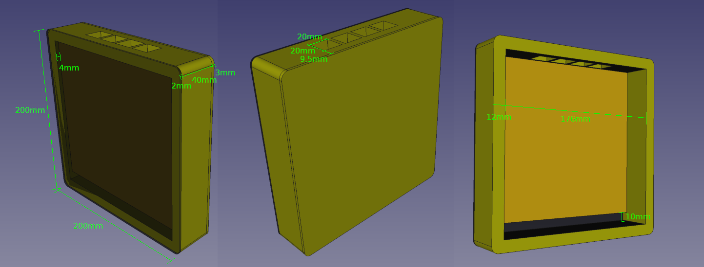
I originally planned to use wood for the square frame (yellow in the 3D model), the display support (orange in the 3D model, put there for the display to be glued on) and the back plate (also yellow in the 3D model). I didn’t expect regular wood to be so expensive though! So I turned to the alternatives, which are still at least made of wood fibres. Plywood, which are made by gluing thin pieces of wood together, and somewhat cheaper. And MDF, which are made by compressing wood fibres (I feel like they are similar to paper, just thicker and stronger. MDF also disintegrates with water, just like paper does.), and quite a bit cheaper. I contemplated on which to use, watched a few videos explaining the differences. It turns out plywood seems to be better because the dust is less fine and thus less harmful for the lung, and does not disintegrate with water. But I still turned to MDF since it’s quite a bit cheaper. It shouldn’t matter much for my project, I guessed.
So I went shopping for tools and materials. I bought:
- A piece of 12mm thick MDF, very large, much more than I needed, but they don’t sell smaller ones.
- 2 pieces of 3mm thick MDF, for some reason they had small piece for 3mm, and the size was just enough for what I needed.
- A large file.
- A set of small files, they only had small files in a set and not individually.
- A handsaw.
- Wood glue.
- 4 clamps.
- A square stick of cheap and soft wood for support while gluing and drilling.
- 8mm drill bit.
Then I started cutting wood into the pieces shown below. The reason I used this shape with protrusions and slots for the side pieces was to increase the surface area of the joints. The 4 side pieces joins end-to-end, and the protrusions slots into the slots. I am not sure if this was worth the effort since this thing doesn’t need to be that strong, but everyone online seems to emphasize how important it is to increase the surface area of joints. And no one on YouTube seems to make a right angled joint by just sticking one end of a piece onto the side of another (a.k.a. a butt joint).

I tried to make the slots on the side pieces by sawing off as much material as the saw can reach and filing down the remaining. It turned out the large file I bought wasn’t suited for the job. I filed for a long time but little material were visibly removed. The small files were obviously going to be worse, since they are even finer. Now making the slots were already this hard with the files I have, making the square holes in the later steps were definitely going to be harder. So I went back to the hardware store, returned the small file set, and bought a set of rougher files. Filing was still slow with the rougher files, but at least my work could have visible progress.
Making the square holes was as painful as I imagined. Drilling the 8mm-diameter circular holes were easy with an electric drill. Removing the rest of the material in the square hole area was a long and tiring process. I filed and filed. Working from afternoon to evening to early night. Had my neighbour complaining about noise. The "square" holes were irregularly-shaped. But I was really tired, so I decided it was good enough and stopped for the moment. It later turned out the holes were not large enough to fit the keys, so I had to enlarge them a little after gluing.
After cutting the 4 side pieces, I glued them together to make the frame. Since the protrusions and slots on the ends of the pieces were not that perfect either, the wood glue did not really make great contacts. But they still held up, which was good enough. I was really scared of the frame turning out to be not square (slanted into a parallelogram), but luckily it was square enough, after waiting 24 hours which was how long the label of the wood glue bottle said I needed to wait.
I also cut the display support and backplate, and glued the former with hot glue.
Since I originally planned the box to be made of wood, I didn’t plan to paint them. Wood grain patterns seemed pretty nice. But now I’m using MDF, I had to paint it so it is not MDF-brown-coloured. The front panel was supposed to be a black translucent acrylic in order for the screen to appear black where pixels were not lit. So I guessed I might as well paint the whole thing black. But also because it was MDF, which disintegrates with water, many paints cannot be used on it, including acrylic paint which was the one of the only paint types I could get in small quantities (I guess most paint containers were designed for people who paint walls and stuff. Buying 2kg buckets of paint just to paint this small thing seemed super not worth it for me.). I went to research online again, and concluded that I should use spray paint cans.
I went to the hardware store once again to buy the spray paint cans. The spray paint cans’ label said I need a primer as well, so I bought a can of flat black paint and a can of primer. Back home, I laid down paper of the floor of my balcony and started spraying. It smelled pretty bad even as I did it on the balcony. It was also a long process, since instructions online as well as the label said I need to wait 15 minutes between each coat. So after painting a few coats of primer and more coats of black paint, it became dark once again. Fortunately I finished before the sky was as dark as I stopped being able to see clearly.
Remember the hot glue I used to secure the display support? One corner came loose after the spray painting. So I added wood glue as it should be stronger than hot glue.
At this stage, I still did not have a way to put the back plate on. It needs to be removable as I need to access the electronics inside. I first thought of using screws, but people said screws in wood becomes loose after unscrewing. A friend suggested using magnets, which I guessed was a good solution.
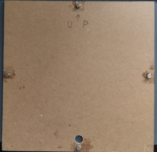
I bought 5mm diameter neodymium disc magnets online. 5mm is a size that can fit into the sides of my 12mm thick side panels, and also a size I have a drill bit for. I drilled a hole on the middle of each of the 4 sides and placed magnets in them. I also taped magnets of opposite poles onto the corresponding locations on the back plate. There were more problems:
- My hand were not still during drilling. So the holes were not in the exact centers of each sides. They drifted a little, enough drift for me to having to adjust the locations of magnets on the back plate. Since the drifts were irregular, I had to lay the frame onto the back plate, poke the magnets into each of the 4 holes, then carefully lift the frame, leaving the back plate with the magnets on the correct location.
- I put the poles wrong! Same poles of magnets repel each other which was the opposite of what I want, so I had to take them off, and repeat the step above.
- 1 magnet pair on each side turned out to be a lot weaker than I expected (Aren’t neodymium magnets supposed to be insanely strong?). I tried drilling the holes deeper and adding more magnets. Eventually I put 4 magnets on each sides of the frame and the back plate, a total of 32 magnets.
- Hot glue could not make a strong bound for gluing neodymium magnets to MDF. I had to buy yet another type of glue: the 2-part epoxy. It came off once more, and had to try again with thicker layers of the glue.
- One magnet on one side of the back plate did not get glued well, and got broken off and stuck inside the corresponding hole on the frame. It seems to have stuck pretty tightly, so I didn’t bother getting it out and gluing it again. It became a feature.
Before putting the front panel on, I glued the display onto the display support, also with epoxy glue.
I wanted the acrylic front panel to be translucent, not semi-transparent, in order to diffuse the light from inside so I don’t see the pixels when they are off. The 200x200mm acrylic I bought from the beginning was translucent when the protective films were on, but I knew it would just be a semi-transparent black when the films were peeled off. Leaving a protective film on the finished product is definitely ugly, so I needed another light diffusing layer. I thought tracing paper would be fitting, but they were actually quite expensive and the stores I went to had them sold out. I found a piece of frosted plastic in alternative, which I think actually worked better than if I had used tracing paper. I glued one side of the acrylic to the cut frosted plastic with epoxy glue. And then with the plastic facing inside, I glued them onto the frame. It came off once and I had to glue again.
By the way, 2-part epoxy glue smelled a little gross, the B part smelled like fish for some reason.
With all these stuff done, I could finally put the electronics in. I glued the key board, main board, the 12V-to-5V converter, the DC power barrel jack in this order, with a combination of hot glue and epoxy glue. So far they have stayed in place.
Completion
Plugging everything in, now it’s the most important moment of truth. If this somehow ended in smoke, I would be very upset. It shouldn’t have any problems though, as I have tested it in every stage. I was nervous, my hands trembled as I plugged in the power, my heart apparently stopped beating for a second before the display came on. But finally, my worries turned out to be needless, as the product of my hard work blinked each second with accurate time on the screen.
I called it a success.
I posted the completed photos on social media once again, and people congratulated me.
Well, it’s not flawless though. First of all, the whole thing looks totally handmade and imperfect. The surface finish is rough, and marks left by dried glue is all over the place. Some unpainted areas shows from the outside. The back plate does not attach well not only because the back of the frame is not flat at all, but also because the glue around the magnets on the back plate formed a chamfer, preventing them from going all the way in. Unlit pixels still shows though the front panel a little, though I guess it’s acceptable. And not to mention the ugly-shaped corner joints and holes for the keys. Also there’s an unoccupied hole on the left side that was supposed to house the reset button I ditched.
Second of all, the temperature measurement is a lot higher than the actual room temperature. The reason is probably the other components are dissipating a significant amount of heat so the inside becomes hot. I didn’t foresee this, I thought this thing wasn’t going to emit enough heat to affect the temperature measurement, I was totally wrong. The amount discrepancy is unacceptably high (like, about 8 ℃). Also because all the other environmental measures (humidity and pressure) are based on the temperature measurement, they are all unusable. I took off the back plate so it’s a bit better, but, like, there’s no back plate then.
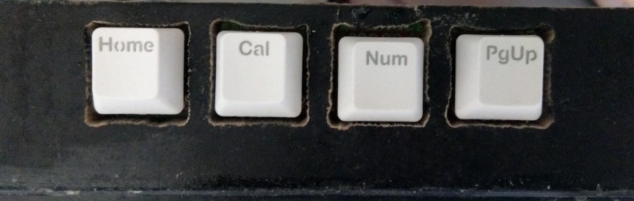
It’s also not really finished. I used Cherry MX key switches, so I got to use key caps designed for a computer. But my buttons are , , and . On a computer keyboard, there are left and right arrows, but obviously no cross and circle. I could use X and O letter keys for and , but they are differently shaped from each other and the arrow keys. I saw online that epoxy resin[8] is something people often use to make custom key caps, so I guess I could do that as well. But that’s another deep rabbit hole I’ll go into later in time. Meanwhile, I just randomly took 4 same-shaped key caps from a pile. They’ll eventually get replaced.
The software also doesn’t have much functionality. The excitement of having WiFi when I switched to ESP8266 did not do a lot. The only thing that currently uses WiFi is syncing time via NTP. I guess I might want to expand the software more later in time, adding countdown timers, stop watches, displaying notifications, and maybe actually playing Bad Apple.
Throughout the making of this project, it made me realize that DIY is probably not going to be a money-saving options oftentimes. The amount of money I spent on tools and materials is something I had lost count on, even though I tried to be as cheapskate as possible. Not to mention the amount of effort and time. I guess if the project is simple, and you have most of the tools, DIYing may be cheaper, I dunno. I wanted a custom digital clock that is not sold anywhere though, so I’d like to think my project was worth it for me.
That’s it. Finally I finished writing this long article which took 2 days to write. I have published all the code and design files, in case you want to know any technical details, or use them as references.
- A microcontroller is a micro electronic component that can be programmed to control circuits. It’s a very simple kind of computer. ↩
- An Arduino Nano is basically the same as the most popular Arduino Uno, but smaller and cheaper. A Uno’s size is way too large in my opinion for something with this little processing power. ↩
- A breadboard is a mainly-plastic board with holes all over them. One can insert electronics and wires onto it and have them work without soldering. ↩
- PWM means turning on and off the LED so quickly that it appears to the human eye as if it’s continuously on but dimmer. Adjusting how much time it’s on verses it’s off changes how bright or dim it appears. ↩
- A key switch is what’s underneath the key cap on a mechanical computer keyboard. Although it’s primarily used for keyboards, in terms of how it interacts with electronics, it’s the same as a regular button. I had the 4 key switches left over from repairing my computer keyboard. ↩
- Buttons are mechanical construct, in the real world, the mechanical contacts will swing back and forth a bit when they are pushed together or released away. So pressing a button by hand once will be seen as the electrical contact has been closed and opened multiple times thus being thought as multiple key presses. Debouncing is the act of removing the effect of these unwanted openings and closings. ↩
- A perf board is something like a circuit board, but with no internal connections and have a matrix holes filling the entire surface (So it doesn’t need to be custom-made). One would insert components on one side and solder and connect them on the other side. Search for images should give you a good idea on what it is. ↩
- Epoxy resin is not the same as epoxy glue, although they are similar. Epoxy glue usually sets faster (tens of minutes), have a color tint, and sold in small volumes. Epoxy resin usually sets slower (about a day), are clear, and sold in larger bottles. Epoxy resin seems like a pretty popular material to make artistic objects, like custom key caps. ↩
View past posts: By Tags, In English, In All Languages